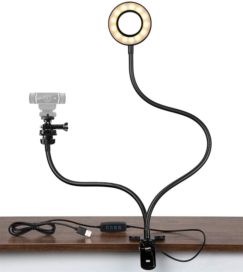
I’ve been setting up my home office with better organization. I’ve recently purchased a ring light for my webcam. I’ve been quite happy with it and how it removes shadows from my video calls. With my new cable organization, the switch for the light has become buried out of reach behind my monitor stand. This blog post shows how I added a remote switch to this webcam light.
The project is simple. This only requires you to solder two wires onto a circuit board, modify the switch case to make room for the second wire, and run this wire to a new momentary switch. We’ll put the new switch into a nice housing that you can mount on the front of your desk.
Adding an on/off switch to a webcam light
Disclaimer: I am not a professional. This is for informational purposes only. Please properly secure all wires, and don’t do anything stupid. Be safe when soldering and don’t breathe the fumes and be careful around wiring in general.
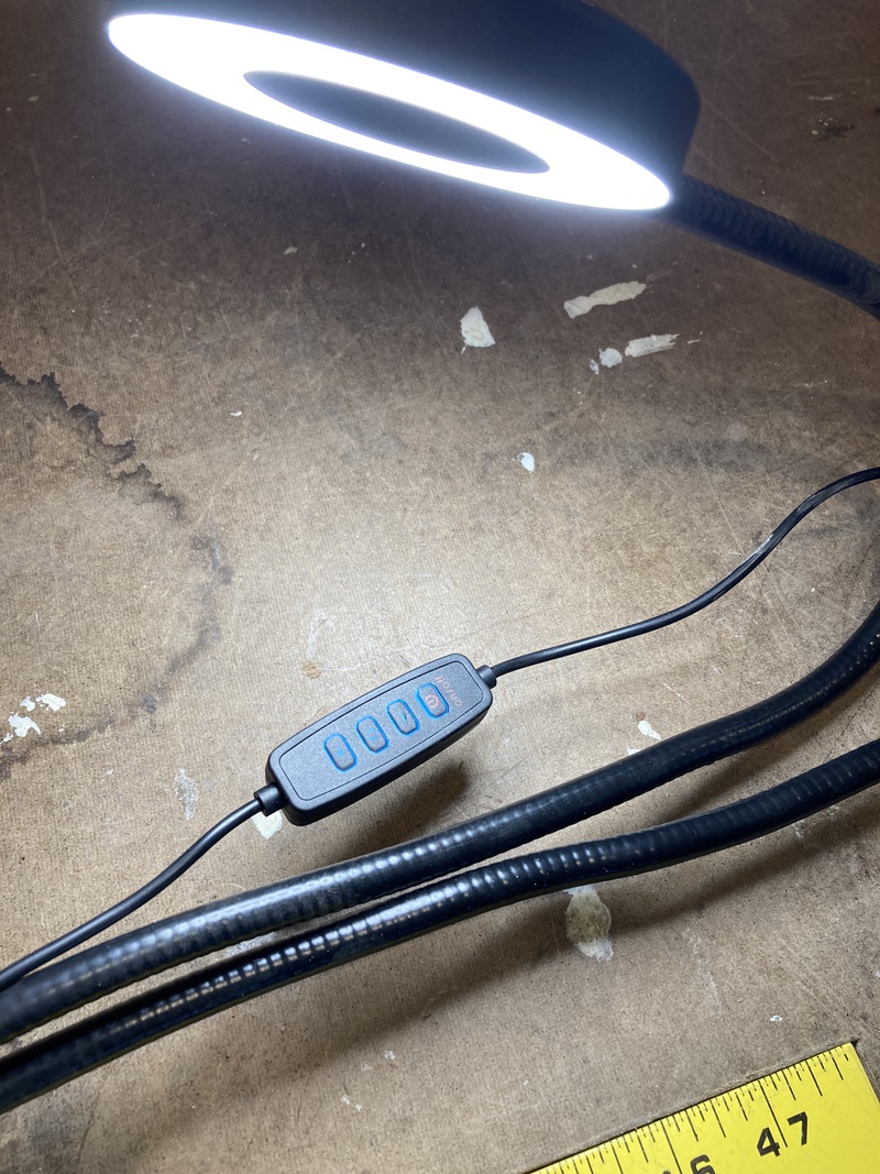
In this post, I’ll share some photos of how to add a switch to a common and inexpensive webcam light. I’ll include a few Amazon affiliate links to the items I used to assemble this. Quite a few of the webcam lights use the same controller and switch. This approach should work for any of these webcam lights. In the photo to the left you can see the switch that controls the color and brightness of the light. We’re going to add a second switch in parallel to the on/off switch.
Materials
Tools
- Soldering iron and solder
- Small screwdriver
- Hobby knife for trimming the switch case
Optional Items
- Hot glue gun for adding some strain relief to the new switch wiring
- Disconnects for making the new switch removable
- Heat shrink tubing if you choose to use the connectors
The Build
Open up the switch case
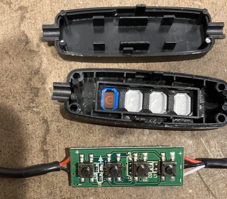
Use a small screwdriver or pick to open the original switch. Mine opened without any damage. There are two tabs towards the center of the sides that hold it together.
Once it’s apart, we can figure out what we need to do. In this photo the switch to the left is for power. It’s a momentary switch, and we can use a multimeter to figure out that only two of its pins are used and they are diagonal across the switch. Put the leads of the multimeter on two pins and then press the button. Try the various options until you find continuity when the button is depressed. It’s a momentary switch and you should get continuity across the switch when the button is depressed if you’ve found the correct pins.
If you don’t have a multimeter you could plug the light into a usb power source (NOT A COMPUTER) and use a short piece of wire to jump across the pins of the switch to figure out which ones are used by watching for the light to turn on.
Solder a new wire onto the board
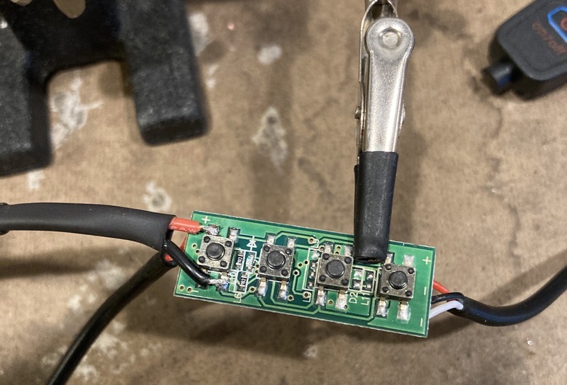
In this photo you can see the new wire added across the switch. It was easier to solder to the top of the board than the bottom. I found that the pins diagonal across the button control the light. Remember to tin the ends of your wires before soldering them to your board.
After you’ve added the new wire, you’ll need to carve out some material from the switch housing to make room for the new wire. In my case I only had to scrape away some of the plastic to increase the size of the exit hole. You might have to cut off some of the plastic. Trim until the housing snaps back together with the two wires exiting the housing.
Prepare our new switch
I wanted a nice looking housing for the new switch. I found an automotive switch housing that would look great under my desk. Unfortunately it has an on/off switch and we need a momentary push-button switch. Fortunately, a helpful reviewer mentioned that the switch could be replaced.
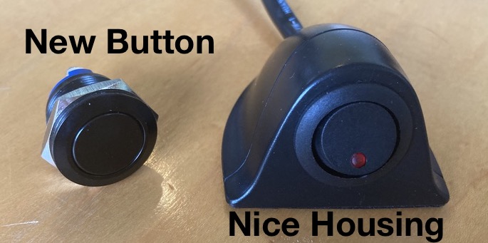
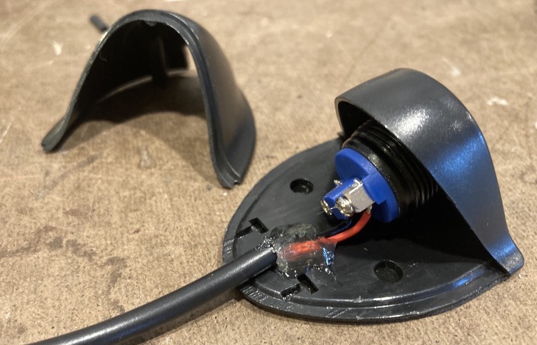
I found that a 19mm momentary switch fit perfectly into the enclosure. The housing comes apart with a little prying. I had to use an X-Acto to cut the adhesive around the edges. See the photo below to see more of that detail. The old switch has tabs that hold it in place, and they are a little fiddly to depress enough to remove the switch.
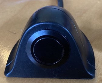
I had to use a pair of angled needle nose pliers to depress the tab on the bottom of the old switch. The new switch has a nicer screw design that makes it easy to install the new switch. I’d recommend putting your wires on before installing the switch as the angle of the switch makes it hard to get to the screws to tighten down on the wires. In the photo below you can see that I’ve added some hot glue to the new wires to add a little strain relief.
The manufacturer has left two small holes in the bottom of the base. I used these to attach the base to the underside of my desk with screws rather than with the adhesive.
Final Installation

Optional Steps
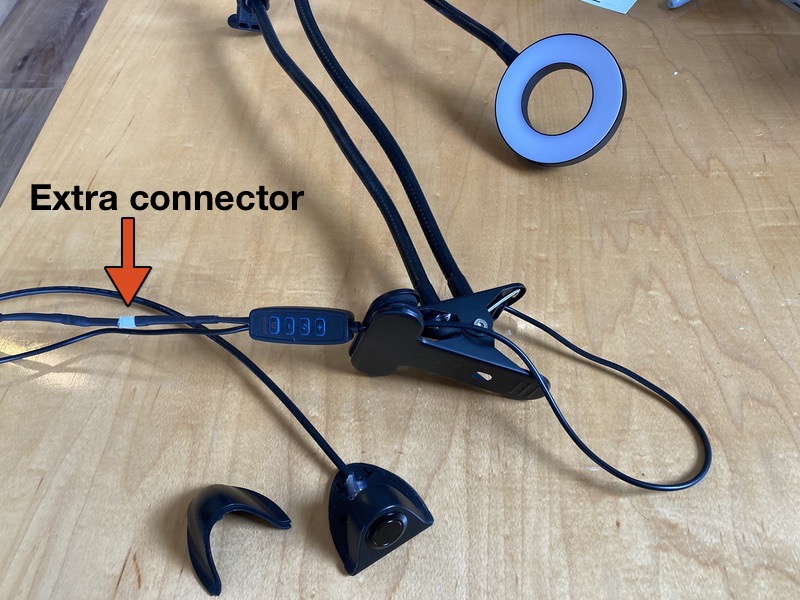
In the photo below, you can see that I put a quick disconnect into my new wire. I needed to be able to run the wire through a hole in my desk to hide my cables. If I’d connected the new switch housing directly to the light, I’d have had a hard time doing that. Adding the connectors took a little extra soldering and some heat shrink tubing. It was worth it to be able to disconnect and reconnect the switch.
