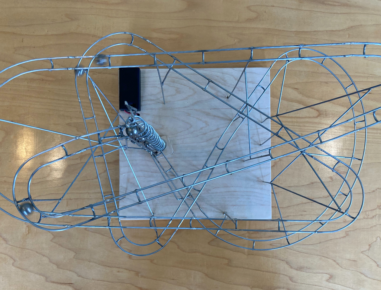
Completed Marble Machine
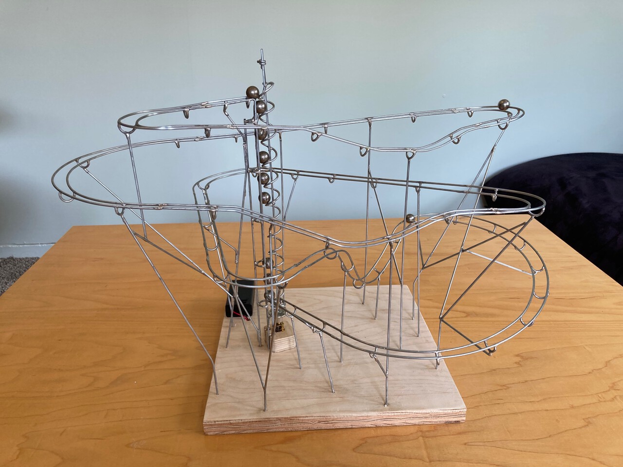
Daniel de Bruin recently posted a wonderful video about How to make a STEEL MARBLE TRACK with basic tools. I was impressed with his creativity and the simple tools that he used to build his track. With some time on my hands because of the COVID stay-at-home orders, I decided I’d give it a go.
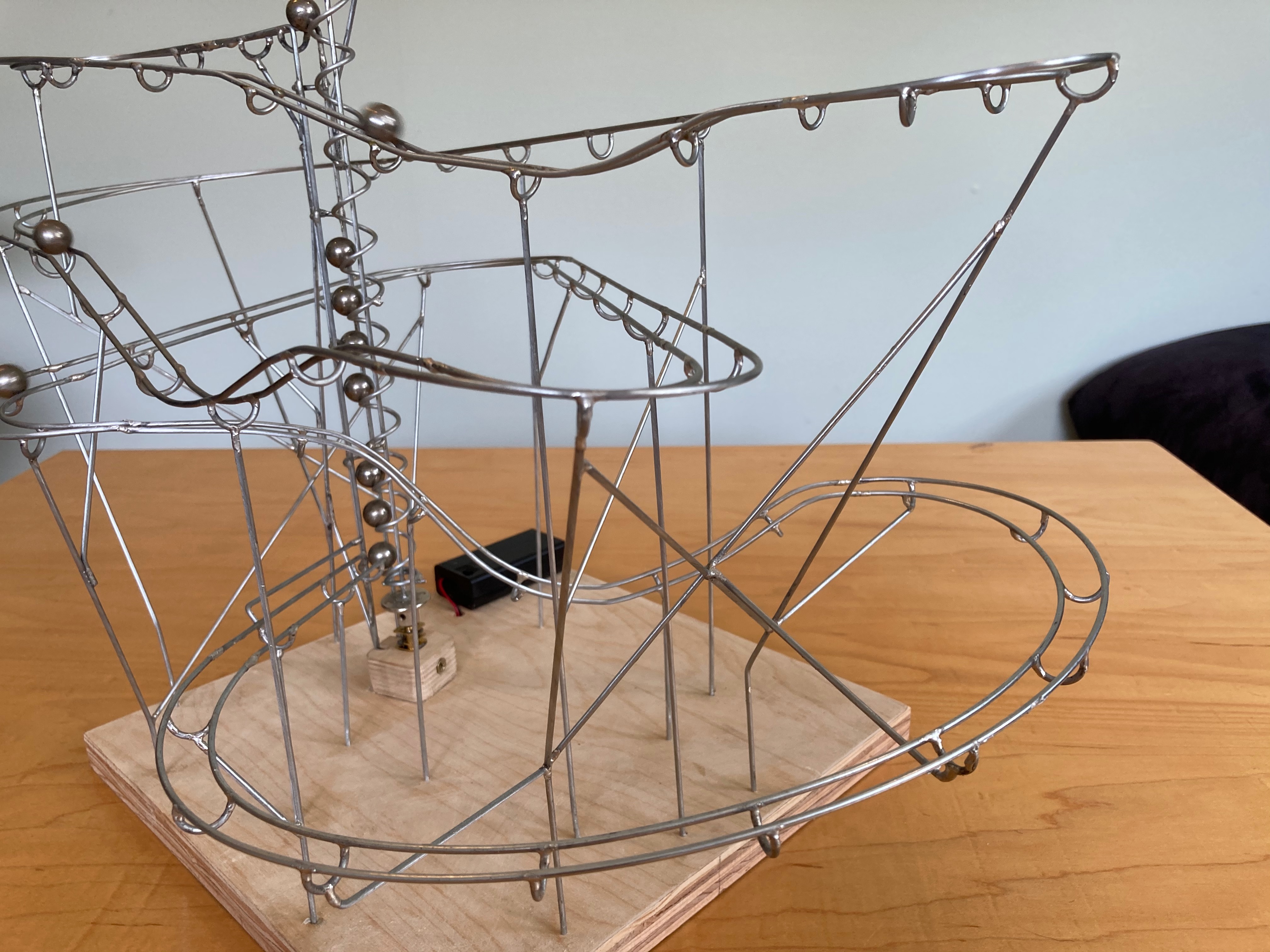
I’m quite proud of my marble machine roller coaster. I did stumble a bit while sourcing the right parts and adjusting the machine until I found the correct measurements. In this post, I’ll add to his how-to with a few more details and measurements that should help you with your project.
If you’ve got questions about any of this or have tips to contribute, please feel free to send me an email.
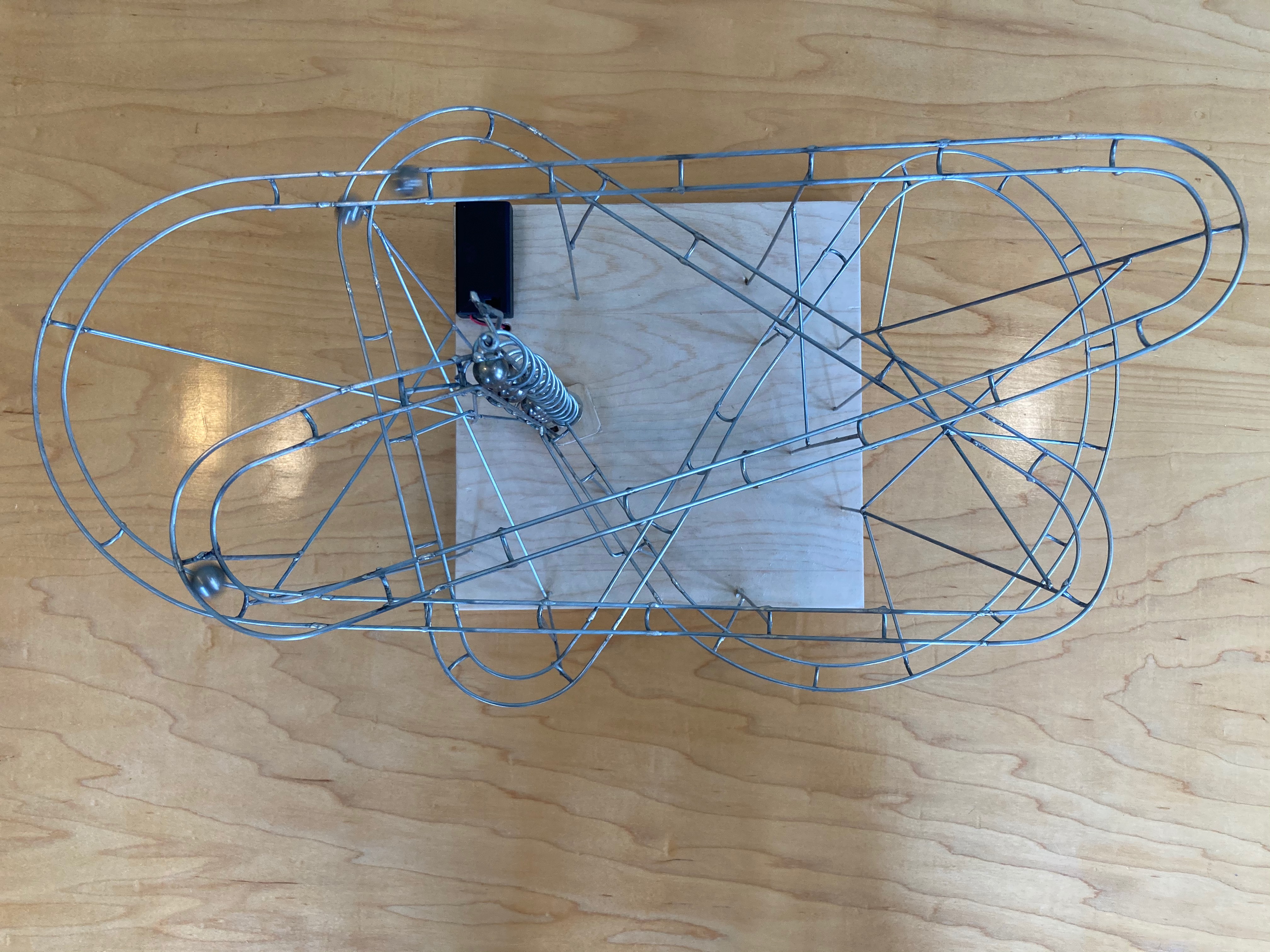
Complete parts and tools list
These are the materials, drive components, and tools I used or recommended. The marble diameter determines several other dimensions, so treat these measurements as a tested starting point rather than a universal plan.
| Category | Part or tool | Specification and purpose |
|---|---|---|
| Track | Steel marbles | 1/2-inch diameter; this sets the lift and connector geometry |
| Track | Galvanized steel wire | 1.88 mm measured diameter; used for the track, lift, and supports |
| Base | Plywood or another flat board | Supports the complete machine; finish it before assembly |
| Drive | DC gearmotor | 3 V and 25 RPM, with a 3 mm shaft |
| Drive | Shaft coupler | 3 mm-to-2 mm; joins the motor to the 1.88 mm lift shaft |
| Drive | Battery box with an integrated switch | Powers and controls the motor without a separate switch |
| Drive | Scrap plywood and a wood screw | Makes the simple motor mount and retaining screw |
| Forming | 1/2-inch smooth-shank rod or bolt | Mandrel for forming the spiral lift |
| Forming | 7/16-inch smooth-shank rod or bolt | Mandrel for forming curved track connectors |
| Drilling | 1.5 mm drill bits | Make slightly undersized holes for the vertical supports |
| Joining | Oatey lead-free plumbing solder and flux | Joins the galvanized wire |
| Joining | Hakko FX888D soldering iron | The temperature-controlled iron I used |
| Joining | Chisel soldering tip | Transfers enough heat into the wire; I used it at 780°F |
| Workholding | Helping hands | Hold braces and joints in alignment while soldering |
| Workholding | Heat-shrink tubing | Covers the helping-hands jaws to prevent marring |
| Cutting | Knipex diagonal cutters | Make clean, precise cuts in the galvanized wire |
| Bending | Parallel-jaw pliers | Bend both track wires to the same angle at once |
| Ventilation | Fume absorber or effective local exhaust | Captures soldering and flux fumes close to the joint |
| Airflow | Small bench fan | Useful only when it reliably moves the plume away without recirculating it |
| Finish | Polyurethane or your preferred wood finish | Optional finish for the base; apply it before assembly |
Jig for Straight Track
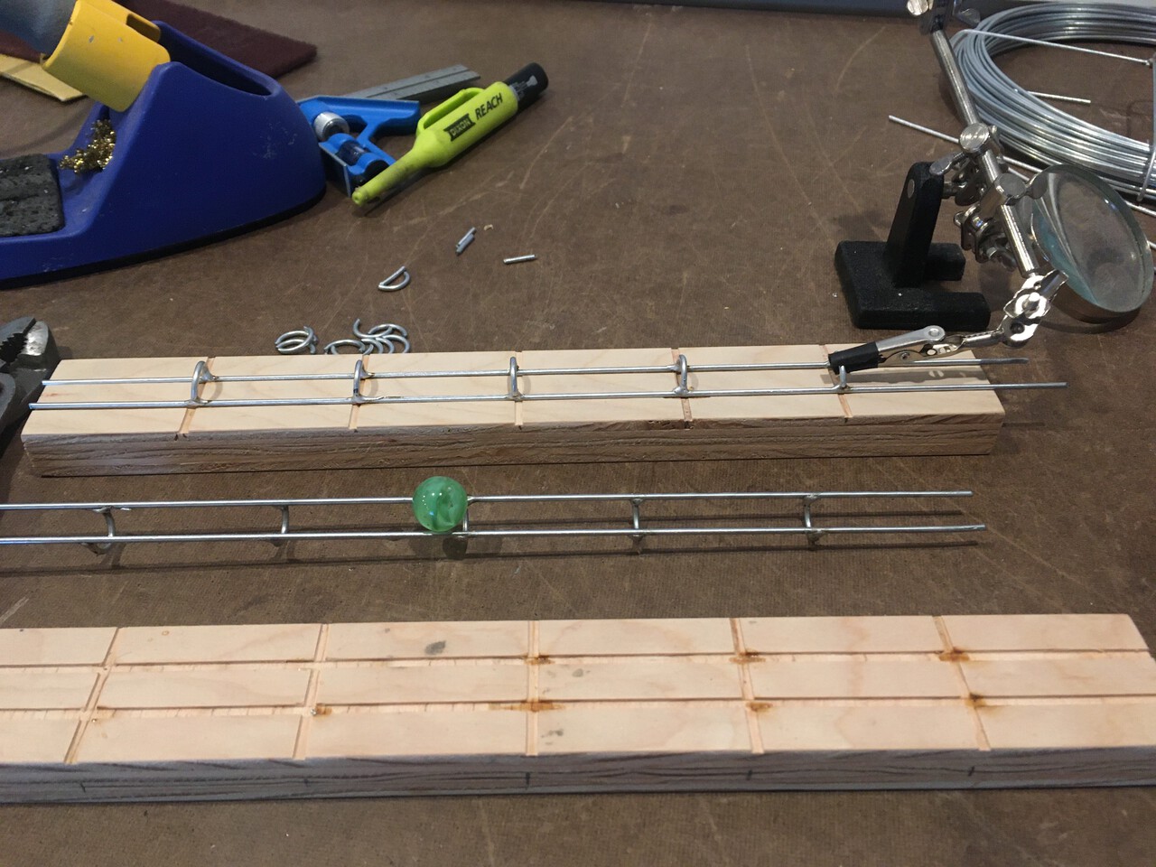
In his video, he marks out a pattern on pressboard and uses clamps to make his straight track pieces. I’ve got access to a table saw, and so I made a proper jig. I recommend you do the same if you can. You could certainly make one with a hand saw and some patience. This ensures even spacing and straight track sections, and because the straight section ends will be consistently spaced it will simplify making the connecting turns.
Helping Hands
In addition to the jig, having a set of helping hands will really speed up your build. You can see them in the photo above in use while building straight track. It’s hugely helpful to be able to set up the helping hands to hold the cross brace onto the track in the jig and then hold the solder in one of your hands and the soldering iron in the other. I prefer to keep heat shrink tubing over the jaws of my helping hands clamps. It prevents marring surfaces and won’t damage wire insulation when you use them on other projects!
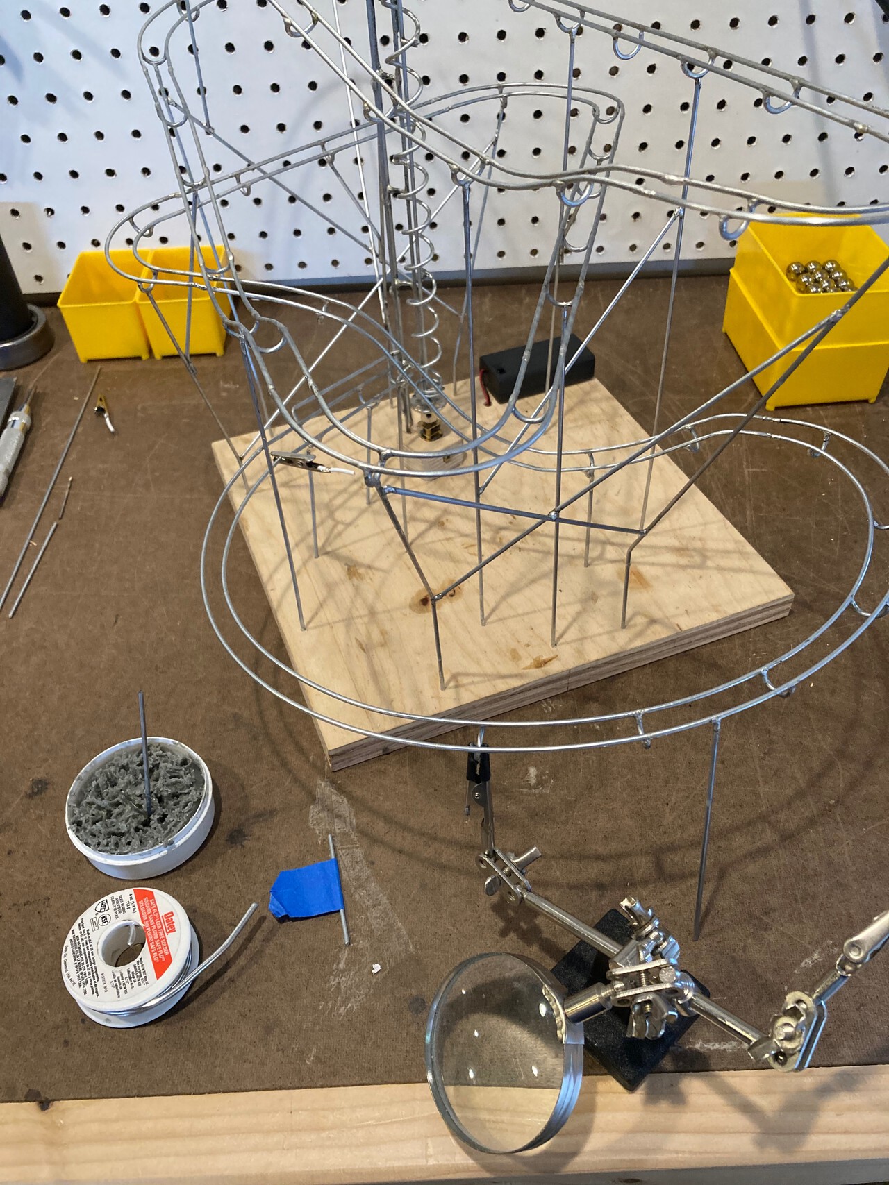
In this photo, you can see the helping hands holding a cross brace in place while I built a long, sweeping turn.
Bolt Sizes
Both the track connection pieces and the elevator lift spiral sizes are dependent on the size of the marble that you choose. In his video, he uses bolts to wrap his wire around to form the curved track connectors and the spiral for the lift mechanism.
The diameter of the bolts that you need is related to the size of the ball. The chrome marbles that I chose were exactly ½”. I found success with a ½” diameter bolt for making the lift spiral, and a 7/16” bolt for the cross pieces. You can find both of these at your local hardware store. Be sure to find either plain unthreaded rod in the metal department, or partially threaded bolts with a smooth shank.
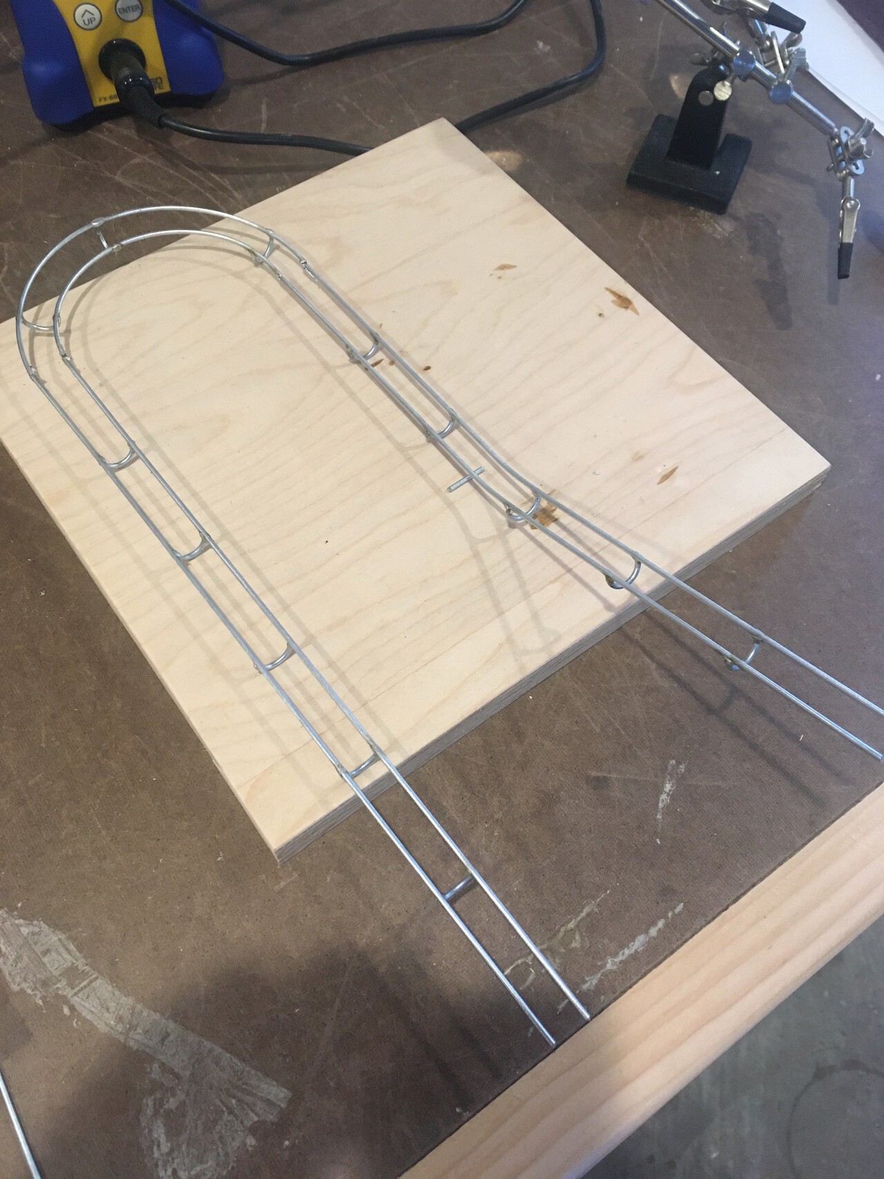
Here’s a photo of some early test track that I made to try out joints and angles.
Soldering Flux and Solder
In the instructional video, he uses Griffon products, which I did not find to be generally available here in the US. Griffon S-39 Universal flux is still listed on the manufacturer’s website, but the 99/1 solder shown in the video may no longer be available. I tried a couple of different options and found good results with Oatey lead-free plumbing solder and flux. This kit contains a paste flux and a copper, bismuth, tin, and silver alloy solder with a rosin core. The solder wetted the wire well and formed strong bonds when I used the flux.
After making a joint, it’s best to immediately clean it with a damp cloth to remove the flux residue to prevent tarnishing the wire. I failed to do this on some of my earliest joints and it shows.
Safety and Fume Extraction
Lead-free solder avoids one source of lead exposure, but it does not make the process fume-free. Heating flux creates smoke, and overheating galvanized wire can expose you to zinc oxide fumes and metal fume fever.
I use a small fan at the bench to move the plume away from my breathing zone. NIOSH recommends local exhaust ventilation for soldering and other hot work because it removes contaminants at the source. A small fan is only helpful if it reliably moves the plume away from you and does not recirculate it toward someone else. Watch the smoke; if you cannot control where it goes, stop and improve the ventilation or use a proper soldering fume absorber.
Keep food and drinks away from the work area, and wash your hands after handling soldering materials and before eating.
Soldering Irons
With soldering irons, you will be rewarded by having a nicer tool. Higher-end models will heat up quicker, maintain a consistent temperature, and will give you better results. In particular, a model with an adjustable temperature can be great for working with various projects. I think that for hobby use there is nothing better than the Hakko FX888D. It’s a joy to use, with high-quality parts throughout. I used a chisel tip set to 780°F, and it worked beautifully.
If you’re just starting out, I’d still stick with Hakko by choosing their temperature-controlled FX60101 or the basic 503F. I don’t own either of these, but I would expect them both to be able to do this soldering.
Vertical Supports
Making the vertical supports is actually quite soothing. I found that I built the track with the bare minimum supports at first while I tested the ball rolling and speed adjustments. Once the track was working well and nearly complete, I added all of the cross bracing. The track will vibrate a fair bit without the cross bracing, and so once you add bracing the track will be smoother, quieter, and more consistent. Remember that as you add bracing you should be building triangular braces.
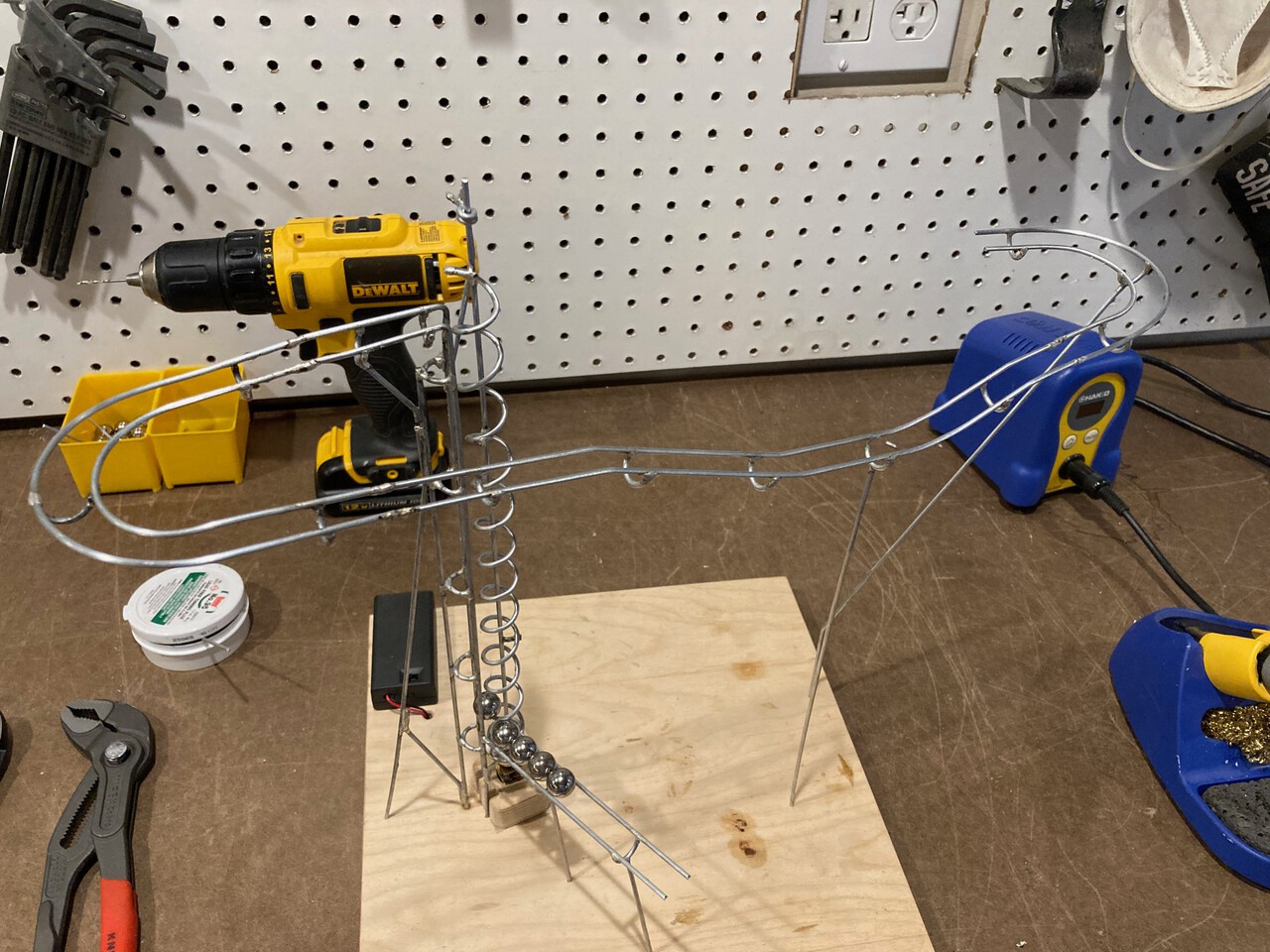
Initially I did my drilling with a spare piece of wire based on this technique from Paul Sellers. I cut a short section of straightened wire and sanded the end into a flat wedge shape. I chucked this into my drill and then used this to make my holes. It worked well, but I eventually ordered a set of 1.5 mm drill bits. I found that these worked better. It does take some force to get the wire into the undersized hole that these bits make. I found it was best to grip the wire with larger pliers perpendicular to the wire and then press down on the side of the pliers while holding the wire firmly to drive the wire into the hole. I also found that in the later cross bracing phase that I had to drill most of my holes from the bottom; there wasn’t access from above with my drill because of all of the track.
Cutters and Pliers
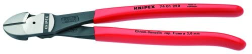
I prefer the Knipex diagonal cutters. They keep sharp edges and had no trouble making precise cuts on this galvanized wire. Even making tiny adjustments to make track ends align was easy with them. I did not find any need for the small bolt cutters that he used in the video.
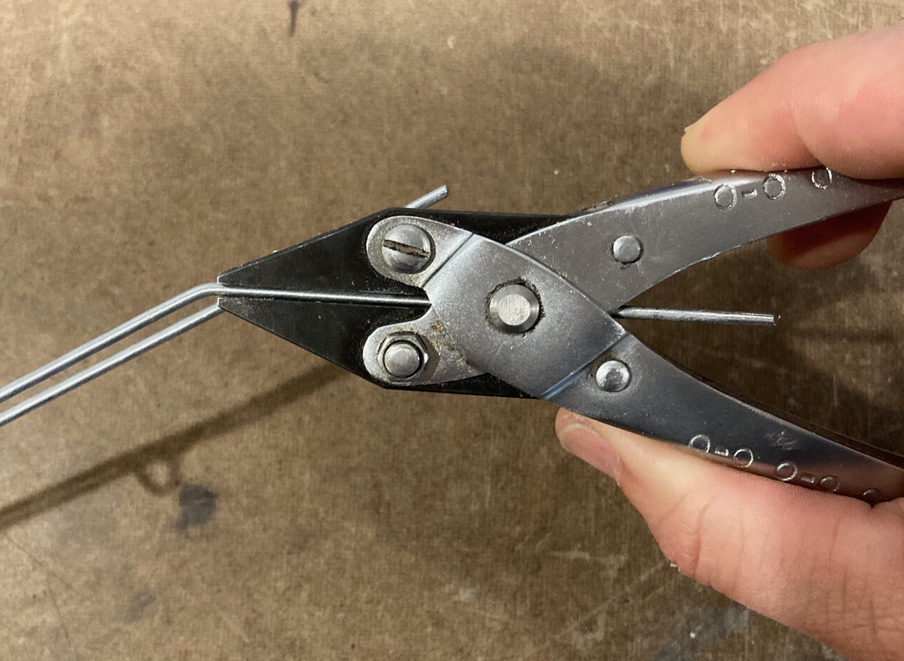
I do have one tool that I’m considering sending him as a thank you - a set of parallel jaw pliers. This is a tool that you’ll wonder how you lived without. Every other set of pliers will only grab wire by one small edge of the tool. These pliers grip with their entire face and hold the wire securely. This allows them to bend both wires at the same time to precisely the same angle. With regular pliers you always end up with a little slop.
They make bending wire at precise positions and to accurate angles quick and easy. As a bonus because of how they open you can pass a wire through the center of the tool to make bends that would otherwise require bent-nose pliers. If you purchase only one extra tool from this blog post, buy these.
Marble Ball Lift Details
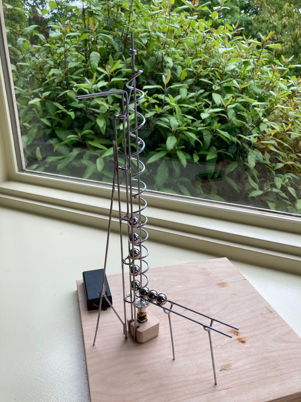
The marble lift is the most fiddly part of this project. In the video, he speeds through it a bit, and while his instructions are good, I had to do a fair bit of experimenting until I had a lift that consistently worked. The most important part of the lift is spacing and the feed track. In the following photo, you can see that I’ve added an extra guide rail. Sometimes when there are a lot of marbles at the bottom and one slams into the back of the row the front one can lift upwards a bit, and that extra rail guides it back into place.
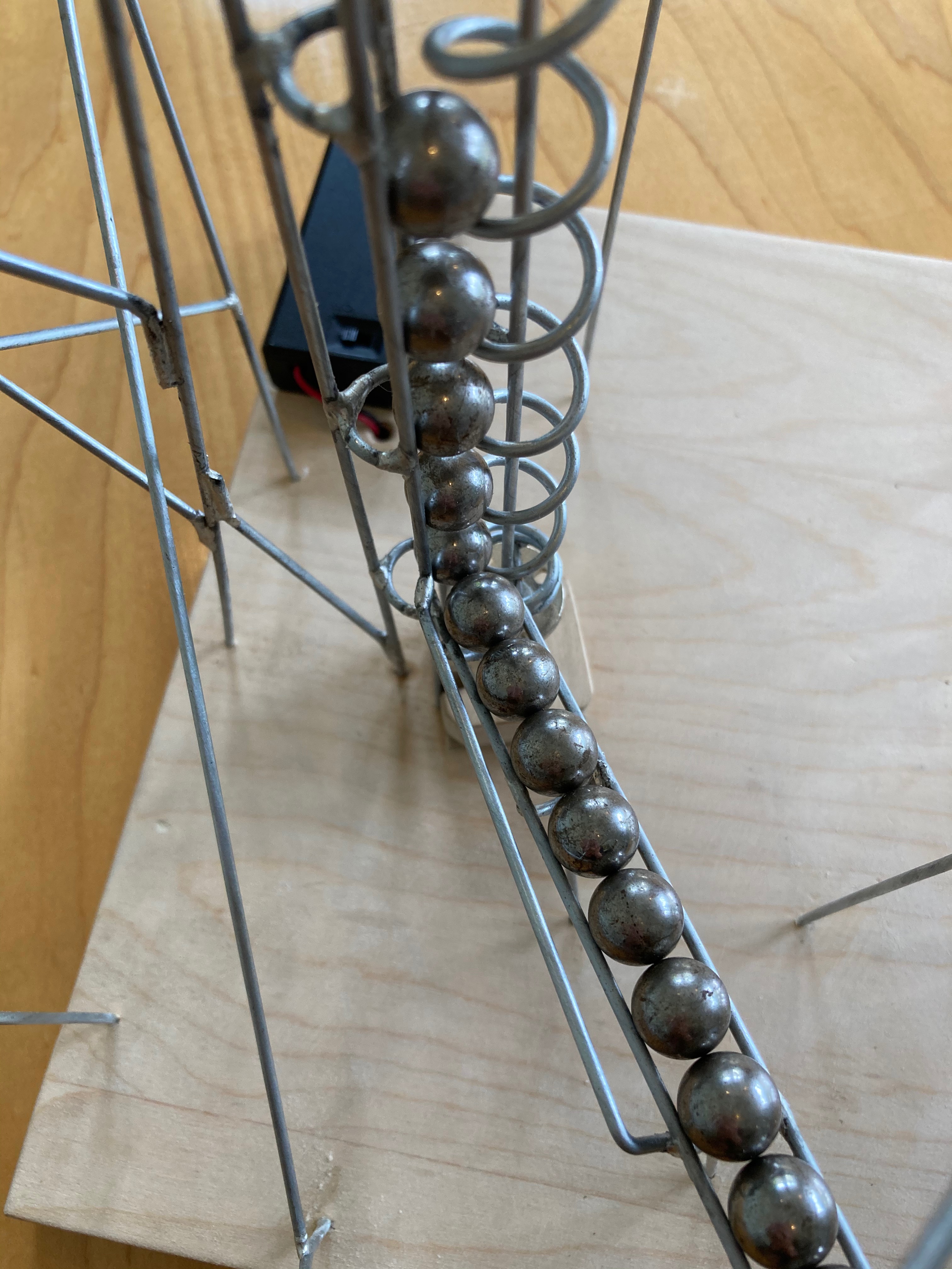
The fixed side of the lift is just a reinforced straight section of track. The center of the lift spiral is not centered between the runners of this track. The lift is offset to one side. If you look closely at his video at 4:48 you can see this detail. Here are the final dimensions of my lift:
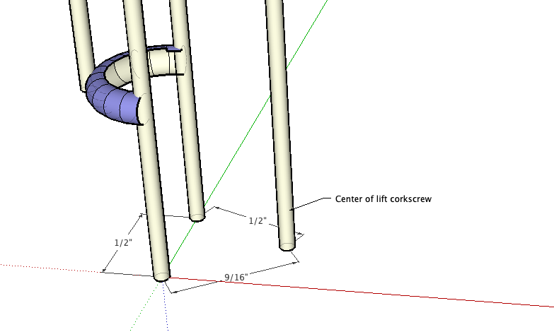
I found the best success with my feeder by having it feed the balls at 90° to the “open face” of the lift mechanism.
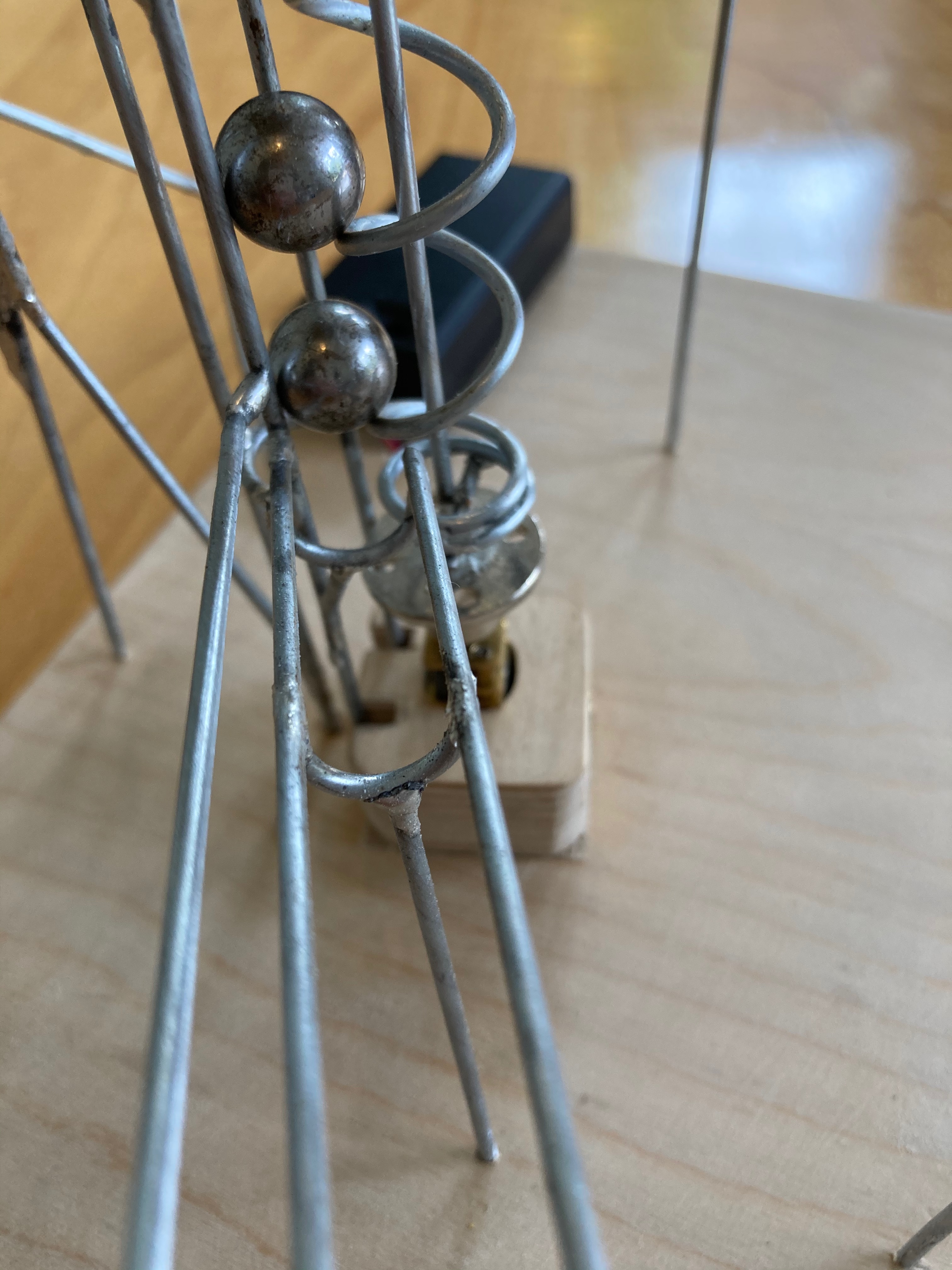
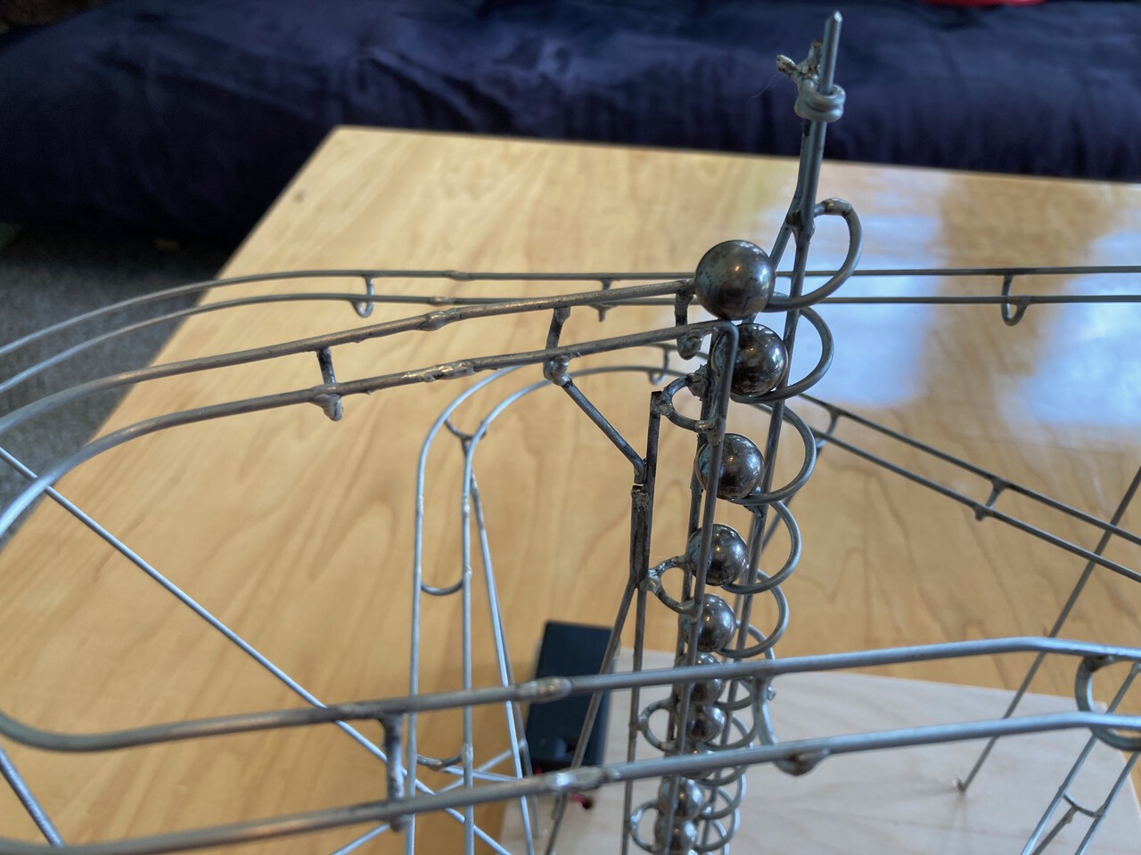
The top of the lift was not particularly difficult, gravity is finally on our side again. I chose to exit directly away from the reinforced rail side. Don’t start off too steep. I did find that the bend from vertical to horizontal needed to be fairly crisp so that the corkscrew lift could effectively push the ball onto the track.
Motor, Coupler, and Battery Box
I went through a few different motors before I found a suitable one that did not need any additional gear reduction. This 25 RPM, 3 V DC motor from uxcell is perfect. It had plenty of torque, didn’t bog down, and is quiet. Delivering about one ball every 2 seconds is a nice pace on the track that I made. I tried both a 9 RPM and a 50 RPM motor and they weren’t right. I think that this 25 RPM pace is the Goldilocks for this size track.
The motor has a 3 mm shaft. The galvanized wire measured 1.88 mm, and I found that a 3 mm-to-2 mm coupler worked great for joining the motor to the central shaft of the ball lift. In some of my photos, you’ll see an alternate coupler that I used before finding this simpler one.
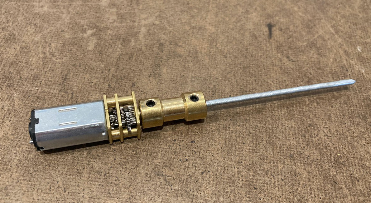
I used a battery box with integrated switch. This further simplified the project. I ran the wires underneath the wooden base to hide them. Note that depending on which direction you wrapped your corkscrew lift you might need to reverse the polarity on your motor so that it spins in the correct direction.
I made a simple motor mount out of a small scrap of plywood with a small hole drilled through it. I used a wood screw with a blunted tip as a set screw to keep the motor in place.
Assembly tips
Make straight track sections first
This will allow you to practice making good solder joints before you need to make the trickier joints in corner sections and track section joining.
Make turns on the workbench when you can
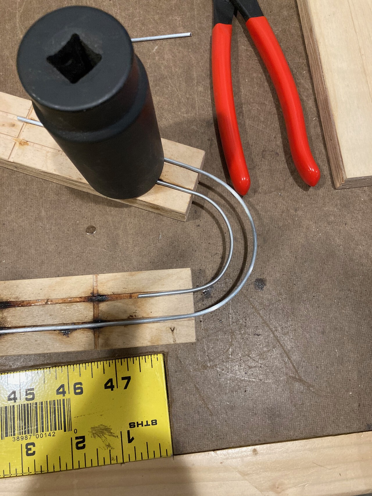
Making some of your turns on the workbench will make it easier to keep your spacing consistent. I found it useful to have two jigs so that I could keep everything aligned. Remember that the outside rail usually does need to be tilted up a bit to make a banked track.
This isn’t electronics soldering
I found that this is a fair bit different from soldering electronics. The parts require more heat input and the joints definitely need enough flux.
Be patient with your solder heat
When making the butt joint between sections of track you’ll find that the track takes a while to heat up enough to make a good joint. Be patient and get both pieces hot enough to ensure a good connection.
Tin your parts before making a joint
In normal soldering, you might be able to heat both wires and then introduce the solder to the joint. Because you’ll sometimes be making joints in the air and holding them in place is hard, you should instead pre-tin both sides of the joint. If you’re joining a new section of track to the existing coaster, you’ll first add flux to one wire end of the track, add heat, and then add solder to the end of the wire. When you’re doing this you’ll have solder in one hand and your iron in the other.
If you pre-tin your soldering iron tip with a tiny drop of solder you’ll get better heat transfer into the wire. That drop of solder will form a thermal bridge to the wire and help it heat up. Once you’ve gotten the wire hot enough you’ll see that dot of solder wet out and the surface tension will break and the solder will smoothly span the gap between the wire and the soldering iron tip. At this point you can add additional solder. Do this same procedure to the track that you’re going to be installing. Each wire end should have a tiny drop of solder on it before you move to the next joining step.
Now that both sides of the track have pre-tinned ends you can join them with only the soldering iron. This leaves your other hand free to hold the new track piece in space without having to resort to elaborate clamping and workholding. Add a little dab of flux to one side of the joint, and then hold the new track piece in alignment with the existing track, and then touch the tip of the soldering iron across the joint to heat both sides. When they are hot enough the solder will join and you’ll be able to align the track. Remove the soldering iron, and then have a steady hand while you wait a moment for the solder to cool. I found that in some cases I needed to get one side joined, then solder the second side, and then jump back to heat the first to make a small adjustment.
Ball speed is controlled by track width
As the track gets wider, the balls will slow down. Narrowly spaced track is both unstable and faster. On narrow track the balls sit higher and roll on a larger diameter and are more prone to jumping the track. If you’re making a section of free-form track this could be an advantage.
Sweat the details early
The more accurate you can make the parts the less trouble you’ll have later in the build. Any errors you make will add up and you’ll end up fighting alignment and spacing issues later. Maintain consistency early and you’ll really enjoy tuning the track for speed and watching it come together.
Paint or finish your base board first
I started tinkering with a board and began building a prototype. I got too far into it to turn back, and just kept going. It was a hassle sanding and applying finish around my support legs. I should have applied polyurethane finish first!
This is really quite forgiving
If you tend to the small details at first, I think you’ll find there’s a larger margin of error than you might expect. The balls will roll over uneven joints, blobs of solder, and will even tolerate fairly flat turns. Don’t be intimidated and just get started!
Enjoy this
I’d really love to see photos of anything you build. Tag me on instagram!