I’ve always wanted an extended idle switch for my Jeep Cherokee. The Police Package XJs were equipped with an extra toggle switch that raised the idle rpm of the Jeep to 1100rpm when it was in park or neutral. All XJs from 1997+ have the ability to do this, but they lack the switch. The switch is something of a holy grail - very few were made and the last of the new old stock (NOS) were sold on eBay for hundreds of dollars. Not all is lost though, as with some ingenuity and a bit of wiring we can make a nearly identical one ourselves.
This project is going to combine a NOS OEM fog light switch with a “fake” extended idle faceplate to provide factory backlighting and switch illumination. We’ll use this hybrid switch to run a relay to activate the extended idle system.
Disclaimer: I am not a professional. This is for informational purposes only. Please use fuses for all wiring, properly secure all wires, and don’t do anything stupid. Please be careful with the project and never connect 12v positive to your PCM by accident!
The Simple Way
You can use a simple toggle switch to connect pin A12 to ground to enable the high idle. But my goal is to replicate the look and function of the factory original switch.
With that out of way, we can continue with this project.
Collect the Supplies
- An Air On Board Extended idle toggle switch This is the “fake” switch. It’s a three wire switch, and we only need the face plate.
- OEM factory fog light switch These are available on eBay. Save one from a junkyard if at all possible.
- OEM factory fog light switch pigtail Retailers don’t usually send the connector that we’ll need with an OEM switch. These can be found on eBay, but go to a junkyard if you can. All XJs have an extra one for the fog light even if the fog light package wasn’t installed. Be sure to clip it with the longest pigtails that you can.
- A relay to run the extended idle system Any four wire auto relay will work.
- Wiring and connectors I really prefer to match factory wiring colors. In particular, the A12 wire from the computer is grey. I solder and heat shrink wiring.
Overview
The Jeep XJ 4.0 in 1997+ vehicles will enter extended idle when pin A12 from the computer is grounded. The factory switch did this on its own. Unfortunately, the closest available switch is a fog light switch. These switches can only control a positive hot wire. We’ll need to use a positive fog light switch to control a relay that will ground pin A12.
I hate cutting factory harnesses, and so I’ve taken an extra step in my installation. There is an engine connector on the passenger side of the motor that contains a gray wire that runs all the way back to pin 12. You can add a new pin to this connector and run this wire to your new relay. This prevents you from having to cut any wires.
Factory Service Manual
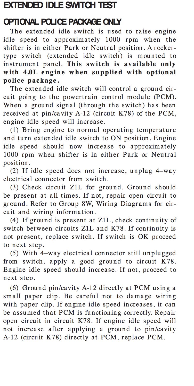
The extended idle switch will control a ground circuit going to the powertrain control module (PCM). When a ground signal (through the switch) has been received at pin/cavity A-12 (circuit K78) of the PCM, engine idle speed will increase.
The FSM has a diagnostic test that outlines the system and offers troubleshooting advice. It’s a great resource. It’s in section 14-43, and I’ve got a screenshot of it for reference.
Circuit Diagram
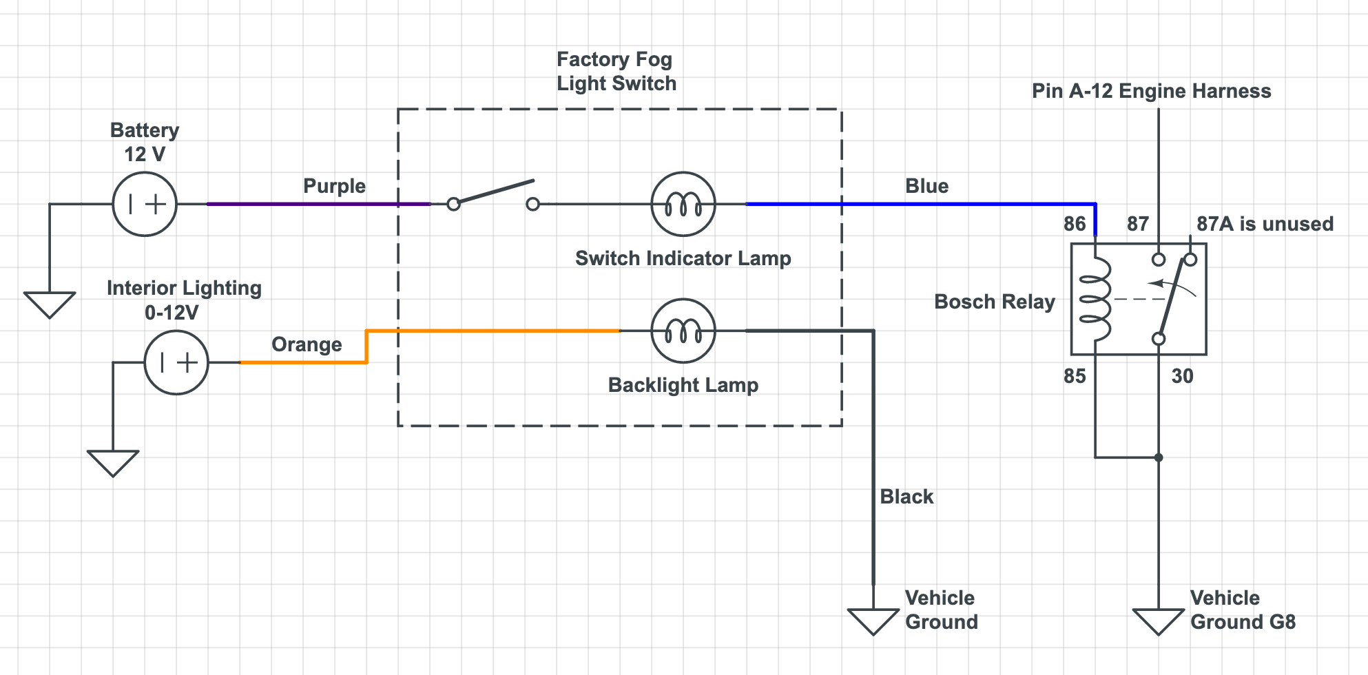
This is the circuit diagram for using a factory fog light to control the extended idle.
Other Tutorials
There’s a fair bit of information about this online. Some of the forum posts are starting to age, and so I’ll host my own photos here to try and preserve this. You can cross reference these, there’s lots of good information in them.
- Cherokee Talk: Making A Ext Idle Switch
- Jeep Forum: EXT idle project
- Cherokee Forum: How to Install a Factory Extended Idle Switch
Extras
I have a fairly cheap benchtop power supply that I really enjoy having around. It makes it easy to mock up these sorts of projects before installing them. I’ve got a multimeter that is no longer being sold. One day I’ll have a Fluke, but until then the little one I’ve got is good enough. For a project like this the continuity tester is especially nice. It’s really nice if it’s a nice loud tone for hearing it over other fans and equipment. Imagine hearing it under the hood while you’re flipping a switch inside the Jeep!
1. The Goal
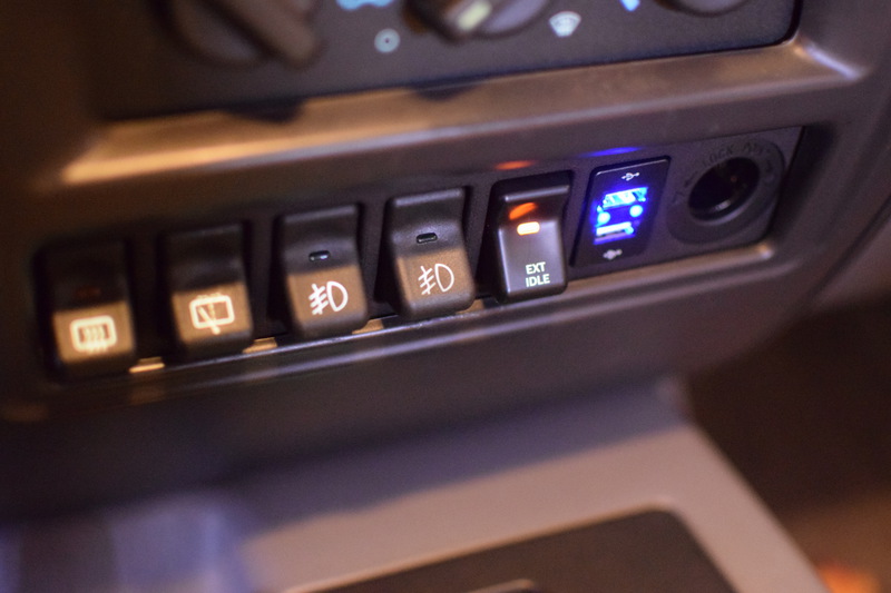
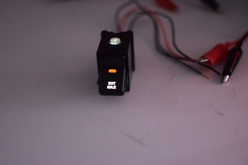
This is the final installation of the switch. This switch has working backlighting and an illuminated orange indicator light when the switch is in the on position. This switch panel is from GCT Enterprises and is the 5 OEM Switch + 1 Toyota Small Push panel. I’ve got more information about it in another post.
2. The Plan
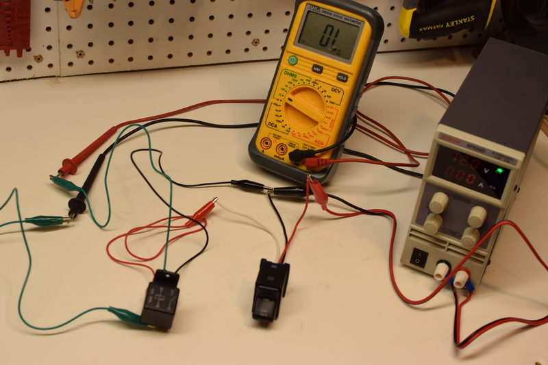
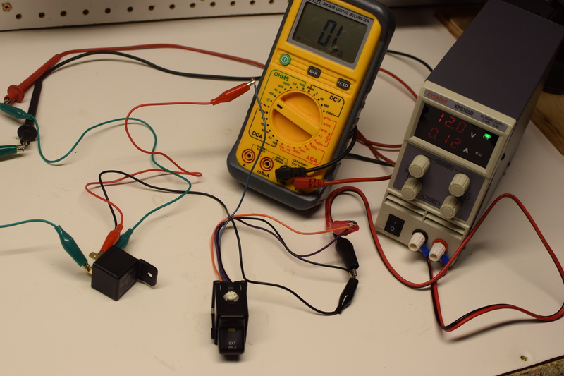
Here is the first mockup with the AOB three wire switch. This does not feature the backlighting, but it’s running the circuit. The multimeter is in continuity mode and is attached across pins 87 and 30. The switch is supplying power to the relay via 86, and 85 is ground. The switch is getting power on red and the white is switched to the relay. The fog light will soon be placed into this with the addition of one more wire to run the factory backlight illumination.
3. Find an OEM Fog Light Toggle Switch
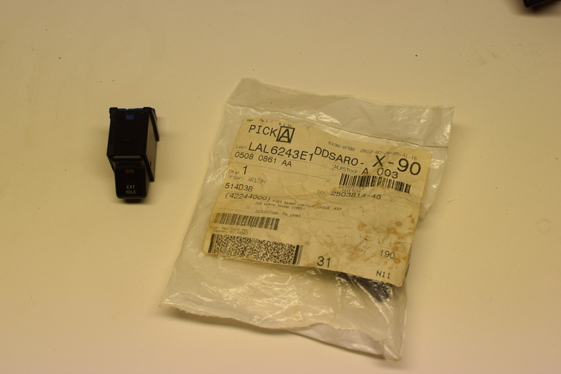
Here’s the OEM fog light switch. This one appears to have lived a long time on a dealer shelf before finding it’s home on my bechtop. We’ll be replacing the Fog Light switch face on this one with the Ext Idle switch face from the other switch.
4. Comparing the Air On Board to OEM Switch
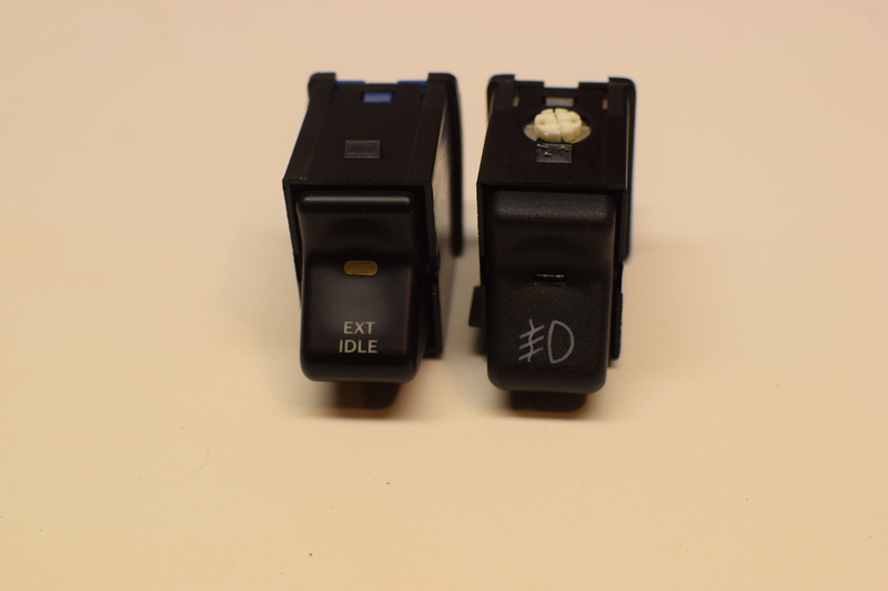
The switch from AOB is really interesting, it’s almost as if it came out of the same mold but without the punch out for the factory backlighting. We’ll be taking both switches apart.
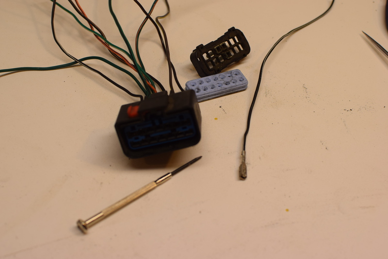
5. Disassemble both switches
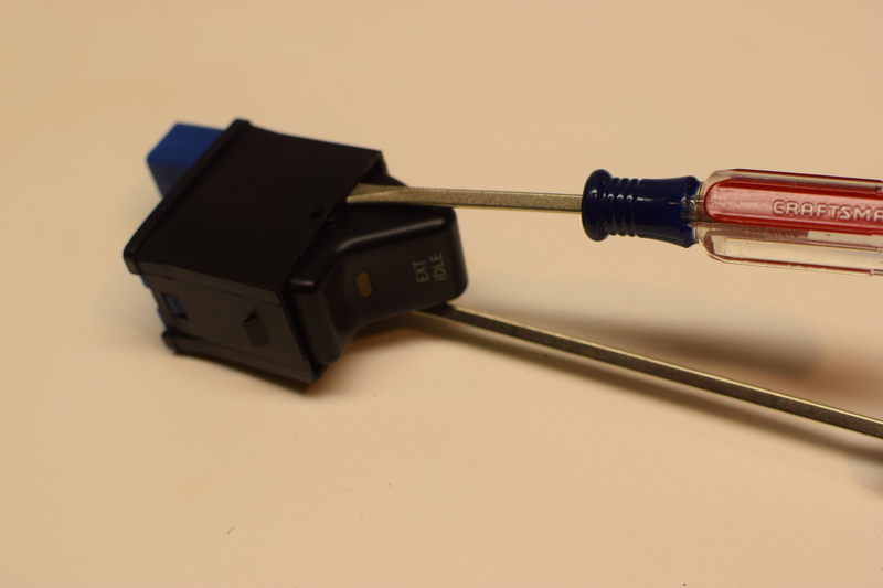
With two small screwdrivers, you can gently spread the sides of the switch to allow the face to be pulled directly outwards.
6. Fitting the new face onto the OEM switch body
The Ext Idle face has a slightly larger pin on one side and won’t fit into the OEM body without enlarging the hole. In my case, both pins on the Ext Idle face were 1/8”. You can ream the small hole in the OEM switch body to fit.
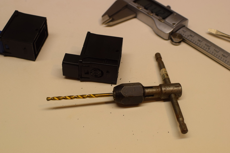
7. Drill the hole to 1/8"

I used a drill bit to do this, and for something so delicate it’s best to do this by hand. I like using a tap handle to hold the bit in this case. Sneak up on the size and test fit it to make sure you don’t end up with a sloppy fit.
8. Assemble and test the hybrid switch
Here’s the first try of the new hybrid switch. This is powering both the orange factory backlighting wire and the purple run source wire. The black wire is grounded.
9. Mock on the benchtop
Here’s the switch placed into our mockup on the benchtop. While this is a pretty simply circuit, I think it’s nice to be able to see it outside of the Jeep.
10. Test operation on the benchtop
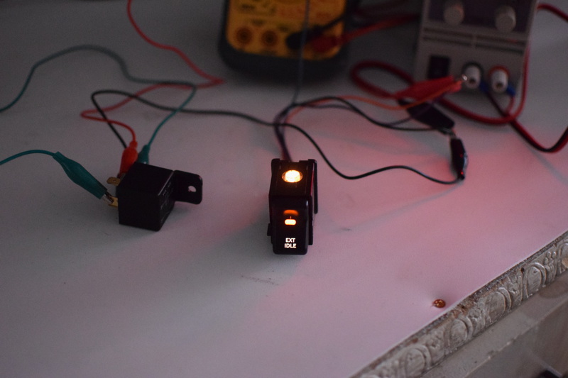
The multimeter in continuity mode is across pins 87 and 30 and will tone when the switch is in the on position. 12v has been added to the factory orange illumination wire.
11. Install the new switch into the dash
I don’t have photos of this step, but it’s very similar to installing new fog light switches. The orange illumination is added to a splice with the other orange wires. The run source wire goes to anything that is on when the vehicle is on. We don’t want to introduce a power draw if the vehicle is off. I chose to use the 12v and ground available from the cigarette lighter from the drivers side.
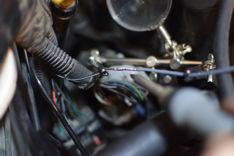
12. Locate the engine connector
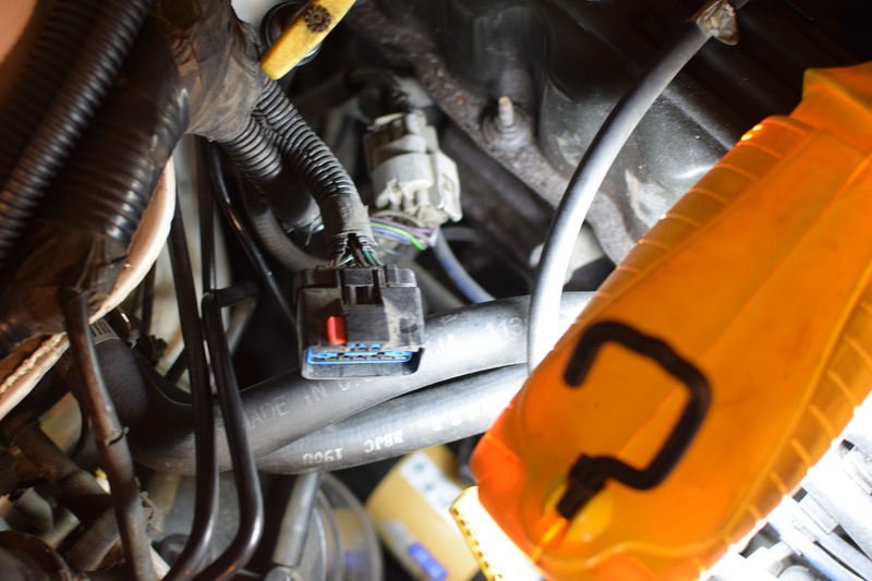
Pin A12 from the computer terminates in this connector. It’s located on the passenger side of the engine and can be identified with the red safety clip on it. In my case, I hate cutting into wiring harnesses, and instead of adding a splice near the PCM or even cutting that wire, I chose to add a new wire to this connector. The grey wire from A12 comes into this connector, and the other side of the connector simply has a blocked port in it’s place. We can pull the little block out and add a new wire.
13. Get a pin from a spare wiring harness connector
I clipped one of these connectors in the junkyard. You can disassemble the connect and remove one of the pins from it. It’s helpful to have a pin extractor set, but you can use a tiny screwdriver to depress the pin underneath the crimped wire end. Pay attention to how this connector is disassembled, if you choose to go this route, you’ll have to also do the same to the one in your engine bay. Note: This is a bit of a warning. This connector is important. If you have brittle plastics on your Jeep, this might not be worth doing. You may have better luck using a wire tap and not risk breaking your connector.
14. Add the wire to the connector and run a new wire
You can gently remove the back from your connector, slide the rubber up a bit and then add your new wire. It’ll be across from the grey wire, and it’s good to check for continuity from that pin to A12 on the PCM. To get to A12, you pull the black wire connector on the PCM that is closest to the front of the Jeep. Each pin is labeled. You can use your multimeter from that pin to the pin on the connector to verify that you’re in the right spot. On the connector back you’ll also need to remove a little plug that was in place of this wire that you’re adding. That plug ass helping to waterproof the connector.
15. Add this new wire to your harness
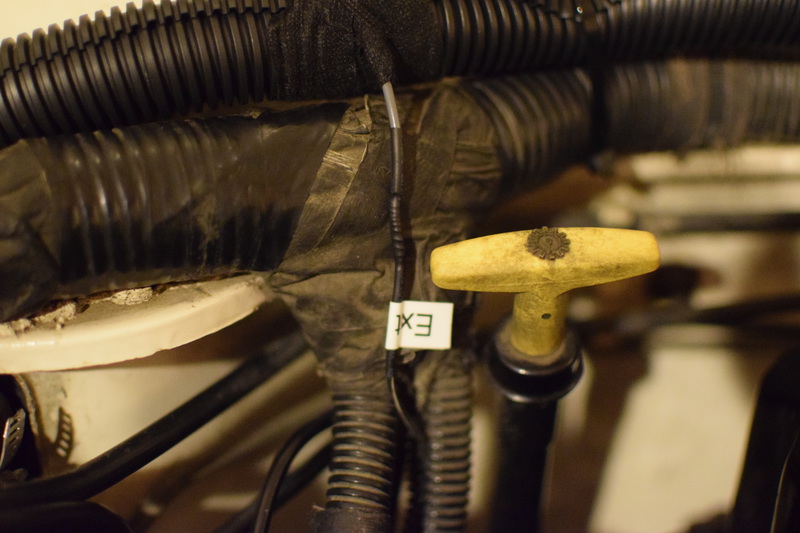
After the wire has been added to the connector, you can connect a new grey wire to it and run that wire to the location where you’ll be keeping your relay. My relay is under my dash attached to the firewall, and is grounded to G8. You’ll find G8 at knee level in the area underneath the steering wheel. It’s a common ground that other things use, and it’s easiest to get to if you remove the trim panel below the steering wheel and the metal shield behind it.
16. Connect this pin A12 to the relay
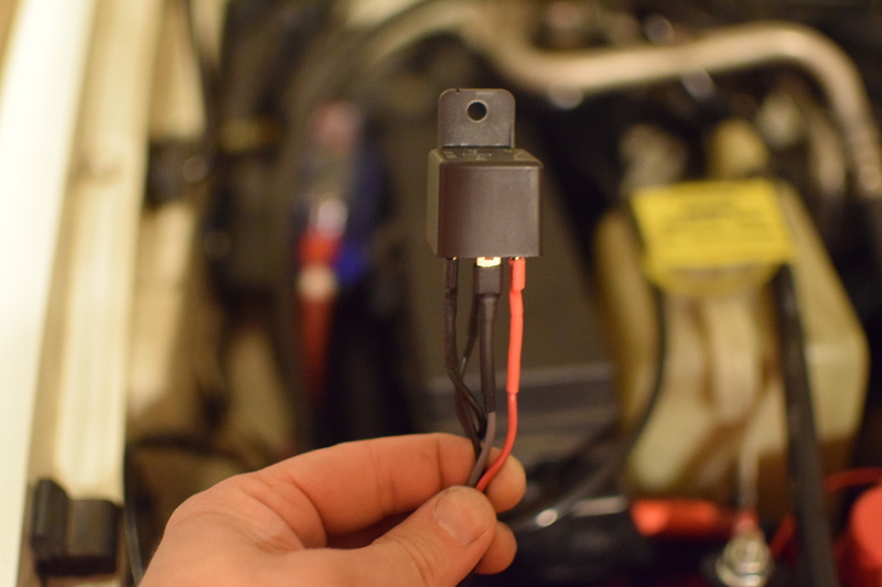
Here’s the relay wired up and done.
Pin 85: Ground
Pin 86: Positive from switch
Pin 87: A12 from PCM
Pin 30: Ground